
Lab Instructor: Syed Abdul Rahman KashifĢ. Observe and plot the load voltage and current waveforms from time 0 to 0.1sec (Output voltage across R & L), (Current through L).

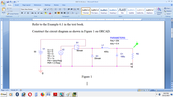
The nominal values for the inverter are as follows: Vs = 120 Vġ. 1 using the graphical front end of ORCAD. Objective: Part 1: Graphically model the square wave inverter shown in Fig. Compare the same with the t he results obtained from the analytical expressions. Study the dc source (input) current and ac load (output) voltage and current waveforms.

Department of Electrical Engineering, UET LahoreĮxperiment DC-AC Inverter: Single-phase Square Wave Inverter Part 1: To get acquainted with the simulation environment for Single-phase Square wave inverter Graphically model and simulate the single-phase square wave inverter i nverter (dc-ac converter) using ORCAD 10.5 and PSpice.


 0 kommentar(er)
